Kavin M. Govindarajan

Robotics PhD at University of Michigan interested in space, robotics, controls, and optimization.
I'm an NSF Graduate Research Fellow and a member of the DASC Lab and the CORE Lab at UM.
I was Park Scholar at NCSU, where I received a B.S. in Aerospace Engineering and a B.S. in Applied Mathematics.
View My Resume
View My LinkedIn Profile
View My Github Profile
Computer-Vision Aided Robotics
Project description: For the 2020 FIRST Robotics competiton, my team wanted to develop a mechanism to shoot foam dodgeballs into a target placed over 10 feet above the ground. In order to ensure the robot would be accurate when shooting, we developed a computer-vision system that would autonomously determine the appropriate parameters necessary for the shooter mechanism to shoot the balls into the target.
Setup

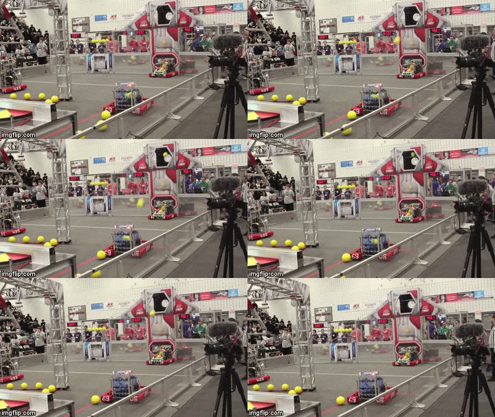
As seen in the GIF above, the target is a hexagonal one that is placed above the ground. The target is outlined by retro-reflective tape.
Our robot utilizes a double-flywheel design for the shooter with a flywheel on top and another flywheel on the bottom. As a result, we have two parameters to control:
- Top flywheel speed
- Bottom flywheel speed
The combination of these parameters can change the flighty dynamics of the ball by introducing backspin, frontspin, or by restriction rotation (commonly known as a knuckleball).
Code/Logic
Target Identification
Our robot is equipped with a camera that is surrounded by green LEDs. These green LEDs reflect off of the retro-reflective tape surrounding the target, enabling for easier identification of the target.
We can then filter the camera input using an HSL filter. Since we are looking for the light that is reflected back, we filter for high luminance. This enables us to ignore the rest of the environment. We chose to use green LEDs, as green is an uncommon color in the environment in which our robot would operate. As such, filtering for our green LEDs would reduce the number of false positives.
After this, since the target is hexagonal, we can eliminate any other further sources noise or false positives by checking the filtered inputs to ensure they fit the hexagonal shape.
Distance Estimation
Once we have identified the target, we then need to estimate the distance of the robot from the target. Since the size/location of the target is fixed, in the camera, the target will appear smaller the further away from the target we are. As such, we can measure the target using pixels in our camera input. We can then relate this to the known real-world dimensions of the target, and using some quick trigonometry, we can identify how far away from the target we are.
We can also use this data to identify our angle to the target. As an offset angle could cause our shooter to miss the target, we had our robot automatically align to the target once it entered the field of vision of the camera. This was implemented with a manual toggle to provide the drivers with more control if needed.
Shooter Control
Through manual testing of the shooter, we generated a lookup table with the following parameters:
- Distance from target
- Top flywheel speed
- Bottom flywheel speed
Once we generated a sufficiently sized dataset, we then developed a function to interpolate between our datapoints when presented with a set of inputs.
In implementation, our computer vision system would identify the distance to the target. It would then pass this value to the interpolation function, which would then return a combination of speeds for the top and bottom flywheels. We then used these values, alongside the computer vision system, to align the robot and shoot the ball into the target. We can see the success of this system in the GIF above.